
The DFR Heritage Telephone Network
Linked Numbering Schemes
This paper has been written so that consideration can be given to the growth of the telephone network of the DFR. Growth is best catered for by the installation of strowger equipment as the present staff have little interest in introducing more modern exchanges.
When several exchanges serve the same general area it is usually most convenient to the user if all the exchanges share a numbering scheme that allows users simply to dial the number required. The alternative is to give each exchange its own numbering scheme and then allow interconnection by the dialling of code digits where the code digits will necessarily be different at different exchanges. The following paragraphs outline satellite schemes that have been used by the GPO/BT in the past.
Direct Interconnections : The simplest arrangement provides each exchange in the scheme with its own initial digit. Dialling the first digit of the wanted number then connects you to that exchange via a direct junction circuit. Such a scheme removes the need for any complex equipment and became the favoured scheme for some of the smaller non director telephone areas.
However the scheme requires each exchange to have its own outgoing and incoming junction routes to all other exchanges and the number of routes rises rapidly as the number of exchanges within the scheme increases. This produces many small junction routes between distant exchanges within the scheme, which individually are rather inefficient and make poor use of the junction cable pairs.
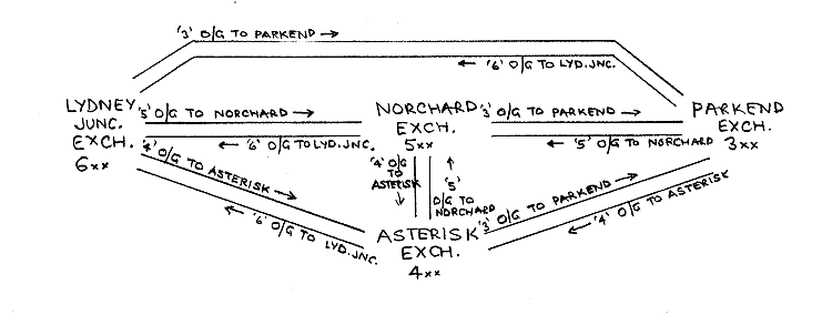
At present we only have four exchanges which would require twelve groups of junctions using this method of interconnection. When the DFR has a further exchange at Parkend Signal Box and if all five exchanges were directly interconnected by junctions, we would require twenty separate groups of junctions. If yet another exchange were added, say at Serridge, we would require thirty groups of junctions. Such a scheme would be getting out of hand and require major cable laying works.
In practice there is another problem with the exchanges. All junctions would terminate on an incoming final selector, yet in Norchard there is only room for two such selectors. Parkend is a little better in that it can accommodate four incoming finals.
In practice therefore this simple scheme is not really suitable for the Dean Forest Railway should we desire to increase the number of exchanges in use.
Linked Numbering Schemes : We need to look back at the older satellite schemes used by the GPO when they too had cable pair shortages but still required linked numbering schemes.
In general one exchange was designated as the "Central" Exchange and all the others in the scheme were known as satellite exchanges. Each satellite had its own junction route to the central exchange and calls to others satellites were made by using the central exchange as a tandem.

Such an arrangement appears to be much simpler and to make savings on line plant. However the line plant savings are offset by the need for complex discriminating equipment in the satellite exchanges. It can be seen that dialling 3, 4 or 5 at Lydney Signal Box requires a call to be made via a single junction group to Norchard. Norchard needs to know whether the caller dialled 3, 4 or 5 when the call arrives at Norchard and yet the number has already been dialled to get the call to Norchard. This implies that the Lydney Junction exchange would need to store the initial digit dialled and repeat it to Norchard. Then there would be a need to store the final two digits dialled as they would be received whilst the initial digit was being pulsed out to Norchard. Lastly the two stored final digits would need to be pulsed out to Norchard for the call to be completed. This was the sequence of events used in the final versions of the satellite exchanges.
Three satellite schemes were used. :
Trombone Working : This was the simplest arrangement and it did not last long with the GPO as it used junction pairs even when the call was between two customers on the same satellite exchange.
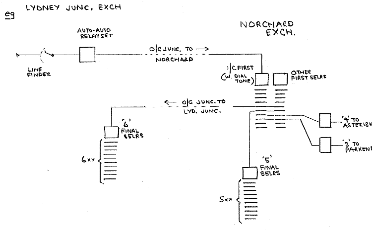
When the customer lifts his handset he receives dial tone from a first selector at the central exchange. It is then simple to route the call to any incoming final at any of the exchanges within the linked numbering scheme. The big disadvantage is that all calls that start and end at Lydney Junction would be routed via Norchard, thus using two junctions (tromboning) for the whole duration of the call. However for such a location as Lydney Signal Box, where most calls are to Norchard, the scheme is quite effective.
Discriminating Repeater Working :
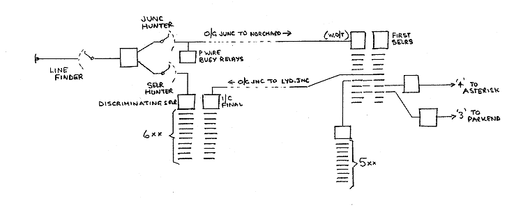
This is a variant on trombone working which was fairly widely used with Siemens 16 equipment. When a caller lifts his handset, he is connected to a discriminating repeater relay set. This has two uniselector hunters. Both operate on seizure. The selector hunter rotates to find a local discriminating selector and the junction hunter looks for a junction to the central exchange. Dial tone is therefore obtained from the central exchange, unless all junctions are busy when the discriminating selector can handle a local call.
When the customer dials, his pulses are repeated over the junction to the central exchange first selector and also to the local discriminating selector. The discriminating selector has a vertical marking bank which allows it to know whether the call is local or junction.
If the call is for a local number, the selector tells the repeater to release the junction for other calls. The selector also restores and now acts as a local selector; in the case of Lydney Signal Box it would be a final selector. The junction will have been held in use only for a very short time.
If the call is for a distant exchange, the selector tells the repeater to release it and continue the call via the junction.
The repeater has the auto-auto facilities built into it and separate relay sets for each junction are not necessary. This is not quite the case, as each junction does need a P wire guard facility to keep a junction busied for some time after it has been in use. This ensures that the equipment in the central exchange has completely restored before the junction is freed for a follow on call.
This is probably an over elaborate scheme for Lydney Signal Box or Parkend, although it would work satisfactorily if implemented.
Discriminator Working :
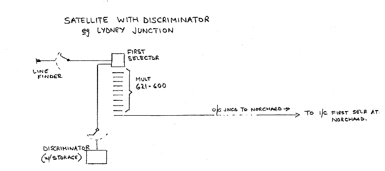
The most used and final scheme for satellite working in a non director area employed discriminators. A caller obtained access to a special first selector which in turn had a discriminator hunter which found a free discriminator. No junction was taken into use at this stage and dial tone was obtained locally.
The number was dialled via the first selector into the discriminator which stored it on a mechanical impulse regenerator. Once the discriminator had sufficient digits dialled in to be able to determine where the call was going, It could start to set up the call via the first selector.
If the call was local, the discriminator could absorb the local routing digit(s) and then repeat the rest of the stored number to the first selector. In this case the first selector will act as a second (or third) selector.
If the call was for a distant exchange, the call would be set up via an otherwise spare level on the first selector and the whole number would be repeated to the central exchange.
In either case, when the regenerator has finished pulsing out the stored digits, the discriminator is released for use on other calls.
This was an elaborate system requiring quite complex exchange equipment using mechanical regenerators, but it did make the very best use of the junction group to the central exchange. It also saved complete ranks of group selectors as one or possibly two digits could be simply absorbed by the discriminator.
We propose to use a variant of this scheme should we ever need an exchange beyond Speech House Road. It has the merit of regenerating the dial pulses on all junction calls. We would expect this to be necessary over the long distances to be dialled.
Growth in the foreseeable future : This is likely to be due to the railway extending further north.
Should the railway extend to Speech House Road, a new cable network will need to be provided along the railway extension. If this cable extension is "bought in" then the conductor size may well be smaller than currently in use, putting Speech House Road out of limits for the Parkend PABX4 exchange equipment. Line limits are around 200 ohms. An extra exchange housed in the new Parkend signal box will cater for long lines going north. It will be of the "trombone" type getting its dial tone from Parkend exchange. The signal box exchange (Parkend North) will however have 3000 type relays with the full winding space employed as "L" relays so that there will be at least a 1000 ohm line limit available.
If the plan to extend to Cinderford becomes a practicality, then a further exchange situated between Speech House Road and Cinderford will be required.
Transmission Limits : If we can extend the cabling network with further 0.9 mm cable, we will probably not be too bothered by faint transmission, particularly as calls between Cinderford and Lydney Junction will not form most of the traffic. If there are faint calls it will not be possible to amplify any junctions because, individually, they will all be short junctions. We would need to move on to VOIP calls made via the internet.
Linked Numbering Scheme for the DFR
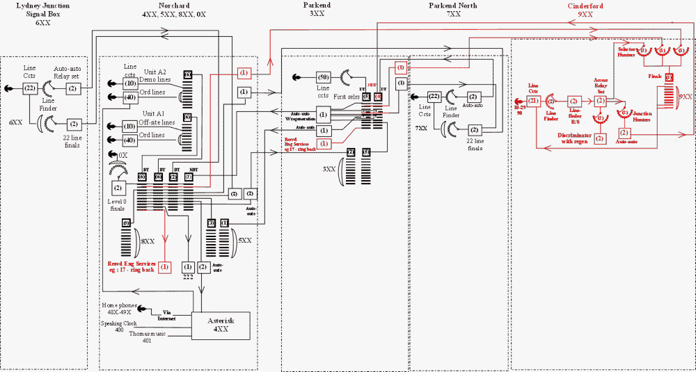
Norchard is a UAX13 with two A units and will be the central or tandem exchange for the system.
Incoming junctions from Lydney Signal Box will terminate on incoming first selectors which will return the dial tone to the caller at the Junction.
Incoming Junctions from Parkend and the Asterisk will terminate on incoming first selectors which do not return dial tone to the callers.
The Norchard Asterisk Exchange will remain much as it is with calls to it coming from level 4 of the Norchard selectors. Outgoing calls to all exchanges will be made via Norchard line circuits as we do not have sufficient spare incoming first selector positions.
Parkend Exchange is of the simple group selector type and does not have any discriminating features built in. The linefinder is also part of the first selector circuit and therefore even simple tromboning cannot be considered.
Dialling 5 gives a caller access to a junction to a Norchard final selector. There is no way of altering this so that calls from Parkend can come into Norchard on a first selector without considerable changes at Parkend. The chosen option was to design and build a new outgoing relay set for Parkend which included discrimination and storage facilities.
The relay set needed five inputs, from levels 4, 5, 6, 7 and 0 and storage of the next two digits. The set would generate the 4, 5, 6, 7 or 0 for transmission to Norchard and would then repeat the two stored digits over a second junction which was terminated on a first selector. One minor effect of this system is that it introduces a short delay between completion of the dialling and the reception of ring tone etc. The final result though is probably the most satisfactory solution for Parkend. Parkend will eventually have two of the storage outgoing relay sets as described above for use on calls to Norchard, Lydney Signal Box and the Asterisk. Incoming junctions from Norchard terminate on incoming final selectors.
Lydney Signal Box Exchange is very simple and trombones any calls via Norchard using first selectors which return dial tone for outgoing calls. The only selectors at Lydney Signal Box are two digit finals attached to incoming junctions and are of a simple uniselector type providing only a 22 line multiple.
Parkend North Exchange is a simple exchange, tromboning outgoing calls via Parkend and receiving incoming calls from both Parkend and Norchard. It is similar to the Lydney Signal Box exchange.
Cinderford has yet to be designed and built but it will be based on Discriminator Satellite technology as this will permit all junction calls to be regenerated.
Future Shape of the DFR Telecoms Network
the trunking diagram below shows how the DFR telecom network is proposed to expand. It involves the provision of a trombone satellite at Parkend North and a discriminator exchange at Cinderford.
Display diagram as PDF
 |
Page provided by John Bathgate
This page was last updated on
8th December 2016 |
|