
Post Office Relays
The 3000 type Post Office Relay is in wide use. Its design has stood the test of time. It is built up from many hundred standard units to enable it to perform a huge variety of jobs.
In essence, a current is passed through a coil of wire wound onto a soft iron core to produce a magnetic flux in the yoke, the basis of the relay to which all other items are bolted. The flux in the yoke attracts the armature, which moves and operates the springsets.
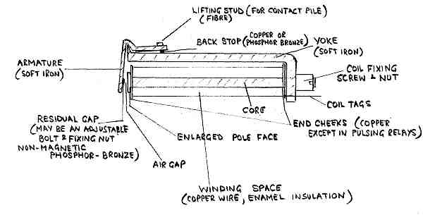
The magnetic circuit is soft iron except for the space between the poleface and armature.
The non-magnetic residual stud on the armature is required to ensure that the relay releases promptly. Without the stud the armature may even remain "stuck on".
The back stop is non-magnetic to prevent the armature sticking in the released position.
The poleface is enlarged compared with the core to obtain a satisfactory magnetic circuit between the coil and the armature.
The relay contacts and the buffer block, which positions the springsets, are bolted to the yoke.
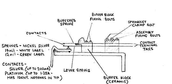

The nickel/silver springsets have two thicknesses. Relays with white labels usually have only a few springs of 14 mil thickness, relays with green labels generally have a bigger spring pile with lighter springs of 12 mil thickness. 14 mil springs are tensioned to a higher pressure than 12 mil springs, thus somewhat equalising the load on the armature.
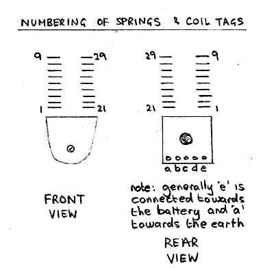 |
Springs and coil tags follow a standard numbering and lettering scheme. It is necessary to take care when counting from the rear as it is only too easy to count the "wrong" side.
The various make, break, etc contact assemblies are also given numbers on circuit diagrams. These numbers are somewhat arbitrary and do not relate to their position in the spring pile. The ATW diagram is usually needed to be able to identify which spring is which as these diagrams show the actual individual spring numbers. |
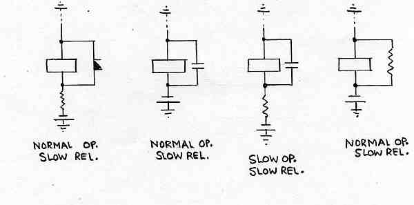
There are many ways in which relays can be manipulated to give various operate and release delays. For delays up to about half a second it is often convenient to place a copper slug in the magnetic path.

A heel end slug affects the collapse of the magnetic field when the energising current is switched off. The collapsing field cuts the slug to produce an eddy current which in turn has its own magnetic field which opposes the collapse. ie It assists the field and attempts to maintain it around the complete magnetic circuit and therefore holds the armature in. However it has little affect at the armature end of the yoke when current is switched on but does delay the build up at the heel end. The relay becomes practically normal to operate but slow to release.
If the slug is applied to the armature end of the core, it opposes both the build up and the collapse of the flux and renders the relay both slow to operate and slow to release.
 |
Short circuiting a winding in the coil is also a well used way of producing delays in relay operation and release. The bottom method is used in the great majority of selectors and auto-auto relay sets. |
 |
There are many other ways of producing short circuit windings under differing conditions. These elements show a sample |
Relays used in transmission bridges in exchanges are part of the final speech circuit and therefore can have an affect on the transmission of the speech. If normal relays were used to feed out current to the users they would have too low an impedance and would shunt some of the speech energy across the line or to earth. This would result in transmission loss.
 |
Such relays are therefore modified by having three nickel iron sleeves surrounding the core to raise the impedance. The sleeves have air gaps in them to prevent them from acting as slugs. They do however reduce eddy currents flowing due to the speech AC variations by their high resistivity and air gaps. This is effective as AC eddy currents tend to run on the outside of a core. |
Transmission bridge relays also have to repeat dial pulses to selector magnets or on to further selectors. They need special construction and adjustment from this point of view as well.
Such relays must keep operating and releasing lags as short as possible and they need to be as equal as possible to avoid altering the pulse make to break ratio. The following measures are usually taken.
1) make the coil end cheeks of bakelite or similar rather than copper which could slightly slug the relay.
2) fit a magnetic sheild around the coil to prevent other relay fields from affecting the pulsing performance.
3) lightly load the springsets. This usually means that the relay needs to be specially adjusted and is marked by a red label on the front cheek, which calls for use of a relay tester to set the relay up correctly.
4) reduce the mass of the moving parts by fitting an isthmus armature.
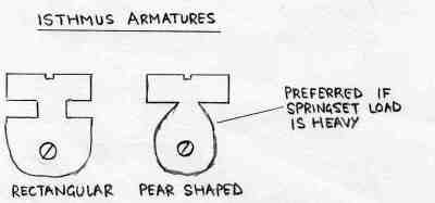 |
The cut-outs in isthmus armatures not only reduce mass but they also restrict the maximum amount of flux that can flow in the relay magnetic circuit. This makes the relay more reliable over a wide range of customer line resistances as the flux cannot vary too much between differing line values. |
Show Page as a PDF (661Kb 3 Pages)
|
Page provided by John Bathgate
This page was last updated on
9th May 2008 |
|

